SDTlib : Logiciel de modélisation, contrôle et simulation des systèmes spatiaux flexibles
La SDTlib (Satellites Dynamics Toolbox – Library) est une bibliothèque Matlab/Simulink qui permet de modéliser le comportement dynamique du satellite. Plus qu’un simple simulateur, la SDTlib a été pensée pour optimiser l’analyse fréquentielle et la synthèse robuste du contrôleur.
Fruit de 15 années de recherche à l’ISAE-SUPAERO en collaboration avec l’ESA, le CNES, l’ONERA et des partenaires industriels, la SDTlib a été validée et utilisée lors de nombreux projets européens de R&D.
Pour des missions d’observation, de service en orbite, de télécommunications, ou tout autre système susceptible de comporter des flexibilités structurelles ou des paramètres incertains, la SDTlib fournit une solution experte et immédiatement opérationnelle d’aide à la conception, sans passer par des développements internes longs et coûteux.
Modélisez chaque sous-système à l’aide de l’interface Simulink


Assemblez pour construire le modèle complet du satellite

Le modèle est prêt pour l’analyse, la simulation, la synthèse du contrôleur…


Une approche multi-corps pour les systèmes complexes
La SDTlib repose sur une approche multicorps : il suffit d’assembler les composants du satellite dans l’interface Simulink pour obtenir le modèle dynamique du système complexe, prenant en compte tous les couplages et degrés de liberté. Ceci permet de modéliser avec précision chaque sous-structure tout en gardant une paramétrisation physique, y compris pour l’impact des incertitudes paramétriques. En particulier, pour les structures flexibles telles que les panneaux solaires ou les bras robotiques, le logiciel inclut des modèles analytiques et des modèles à éléments finis pour les formes géométriques simples (plaques et poutres), et une interface avec Nastran/Patran pour les géométriques plus complexes. Cette approche permet également de modéliser des mécanismes complexes, par exemple les mécanismes d’entraînement des panneaux solaires (SADM), ainsi que les microvibrations que ceux-ci peuvent générer par des imperfections dans la boîte de réduction ; les roues à réaction sont un autre exemple, avec prise en compte de l’effet gyroscopique mais aussi de possibles balourds générant des perturbations harmoniques.
Un modèle dynamique entièrement paramétré
La SDTlib permet de définir tous les paramètres incertains (fréquences de résonance, inerties, etc.) ou variables (comme l’orientation des panneaux solaires). Elle fournit un modèle unique contenant toutes les configurations paramétriques, à partir d’un seul modèle à éléments finis pour chaque sous-structure flexible, et sans nécessité d’échantillonner l’espace paramétrique. Une fois compilé, le modèle est prêt à être utilisé avec les outils de contrôle robuste de Matlab afin de concevoir automatiquement un contrôleur stable et robuste, accélérant ainsi le processus de conception et de validation.
Exemples d’applications
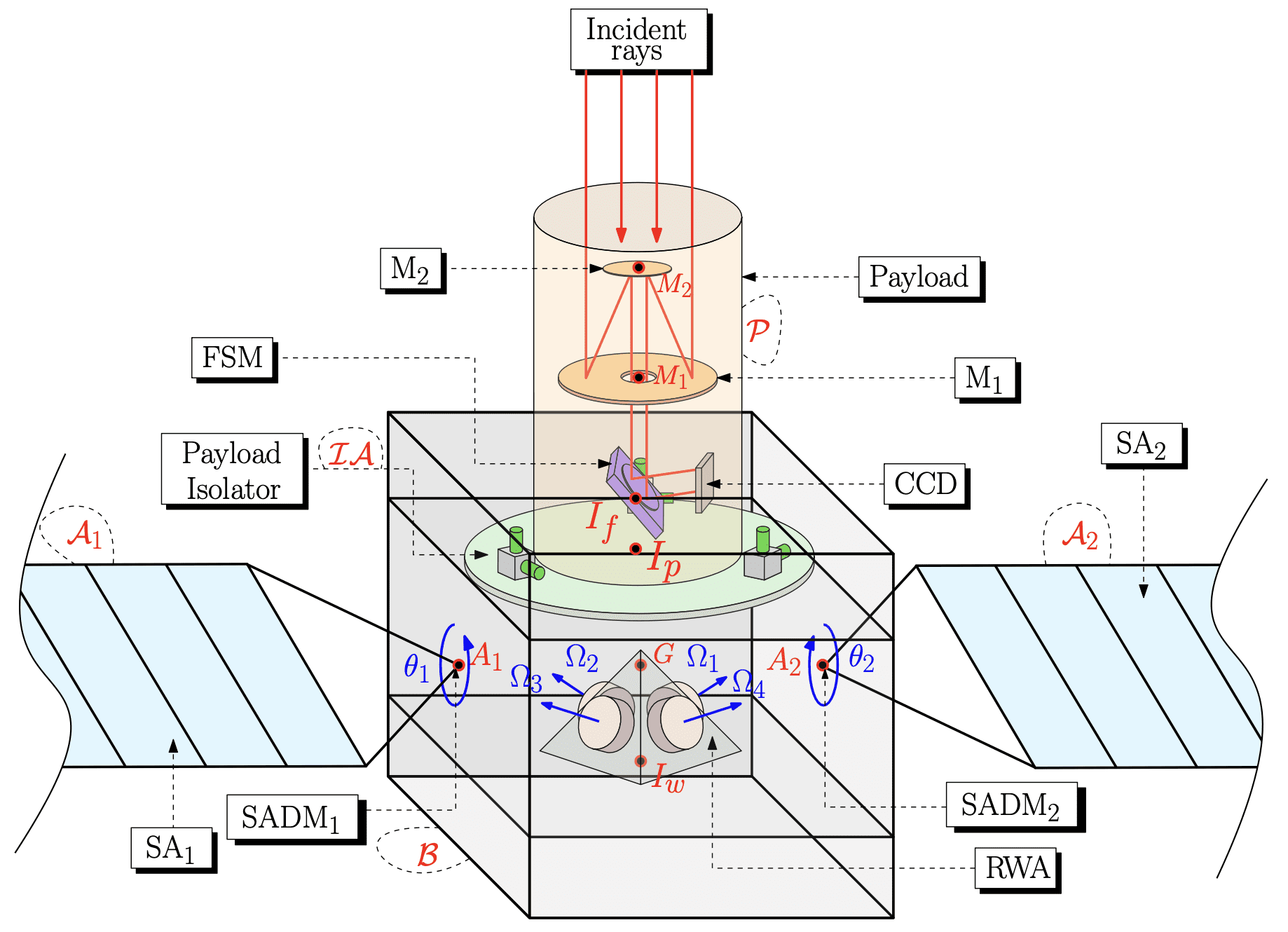
Pointage de précision pour une mission d'observation
Cette étude de R&D portait sur l’optimisation de la performance de pointage d’une mission générique d’observation. Le satellite considéré comportait de nombreux éléments flexibles et des mécanismes sources de vibrations. Le système a été entièrement modélisé avec la SDTlib pour analyser la propagation et l’impact des diverses sources de perturbation sur la ligne de visée, et comparer rapidement plusieurs architectures de contrôle.
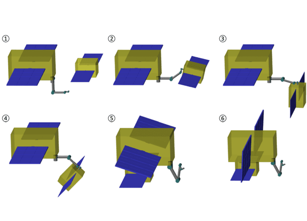
Manipulation robotique pour du service en orbite
Cette étude de R&D portait sur la modélisation haute-fidélité d’un scénario de service en orbite. La SDTlib a permis de modéliser le satellite de service et le client, chacun avec leurs propriétés de masse, d’inertie, modes flexibles, etc, puis le système complet après amarrage. Ce modèle, paramétrisé avec les incertitudes mais aussi les positions des liaisons du bras, a a été utilisé pour optimiser un contrôleur qui prend en compte les changements d’inertie et de modes flexibles au cours des opérations de proximité.
Pour toute information complémentaire, n’hésitez pas à nous contacter.